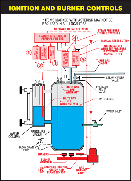
In the last issue, we took the necessary components and cobbled them together into a configuration that controlled the maintenance of the proper water level inside the boiler. That was ½ the of the picture. Controlling the fire or “firing” the boiler is the other half. In this issue, I’ll describe how the different components are organized into a safe and reliable system to convert the water inside the boiler into steam and maintain that steam within a specific pressure range.
PART 2- CONTROLLING THE FIRE
The fire is controlled by simply turning a gas solenoid (an electrically operated valve) on and off. Sounds simple, but there are a lot of things that need to happen to accomplish this safely. An Ignition Controller coordinates the activities of the different sensors used for this opening and closing of the gas solenoid. These Ignition Controllers may be called a Honeywell or Fire Eye (and other brand names depending on the boiler manufacturer).
Ignition Controllers usually do 6 things (refer to the #(number) in the illustration):
1. The output from the 1st low water sensor located in the Water Column is monitored #1- when the water level drops below the probe, the gas solenoid is shut off, and an audible alarm is sounded. When the water level is at or above the sensor, the gas solenoid circuit is enabled (if other conditions are met, the flame will go back on), and the alarm will stop.
2. The output from the 2nd low water sensor located in the Pressure Vessel is monitored#2- when the water level drops below the probe, the gas solenoid is shut off, and an audible alarm is sounded. The alarm will continue until the water level is at or above the sensor and a manually operated switch is pressed to clear the alarm condition. The gas solenoid circuit is then enabled (if other conditions are met, the flame will go back on), and the alarm will stop.
3. The high-water sensor output (not found on all boilers) in the Pressure Vessel is monitored#3- when the water level is at or above the probe, the gas solenoid is shut off, and an audible alarm is sounded. The alarm will continue until the water level is below the sensor and a manually operated switch is pressed to clear the alarm condition. The gas solenoid circuit is then enabled (if other conditions are met, the flame will go back on), and the audible alarm will stop.
4. The condition of the operating pressure control switch is monitored #4.- This switch normally has closed contacts that open when a preset pressure in the Pressure Vessel is reached and closes again when the pressure drops to a preset pressure (the difference between this switch’s opening and closing pressure setting is called the differential). The opening of the gas solenoid valve can only occur if the operating pressure control switch is closed. This means the upper limit of the boiler operating pressure had not been reached.
5. The condition of the high-pressure safety limit switch #5- This switch normally has closed contacts, which open when a preset pressure in the Pressure Vessel is exceeded and requires a manual reset. Opening the gas solenoid valve can only occur if the high-pressure safety limit switch is closed. When this switch opens, it indicates the safety limit of the boiler operating pressure has been exceeded. Usually, there is no alarm indicating this condition.
6. Gas ignition is monitored #6- Before the gas solenoid valve is opened, a smaller pilot solenoid valve is opened, and an electric spark is used to ignite a small burner to act as an ignition source for the larger volume of gas released by the gas solenoid valve (see section B on illustration). If a flame is not sensed after a short preset time, the pilot solenoid valve is shut. Depending on the Ignition Controller, it will try a few times for a successful pilot ignition, then go to an alarm condition requiring a manual reset. Most ignition controllers provide a visual indication when an ignition fault has occurred.

Most Ignition Controllers have visible indicator lights; use a smartphone to record light patterns while the boiler operates properly. Referring to that video will go a long way in enabling you to troubleshoot ignition problems, perhaps saving an expensive, unnecessary service call.

Bruce Grossman
Bruce Grossman is the Chief of R&D for EZtimers Manufacturing. EZtimers is the manufacturer of the new EZ DOSE boiler compound manager and return tank level control which replaces that troublesome ball float valve in the condensate return tank and automatically adds the correct amount of boiler compound to the return tank preventing the oxygen corrosion and scaling. Our SAHARA and DIB-M high purity separator water mister/evaporators provide a thrifty, legal method to get rid of the separator water generated by your dry-cleaning machine. See our Ad in this issue and for further information on EZtimers products visit www.eztimers.com Please address any questions or comments for Bruce to bruce@eztimers.com or call 702-376-6693.

